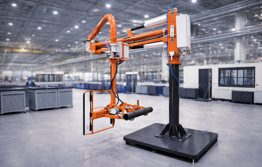
How to Size a Pneumatic Manipulator for Your Application
Sizing a pneumatic manipulator isn’t just about weight. Learn how engineers account for reach, load moment, and control in real applications.
Matt Seibert, Director of Engineering
3/18/20264 min read
Sizing a pneumatic manipulator isn’t just about weight.
In fact, many lifting applications fail not because the load is too heavy—but because the system wasn’t designed for how the load behaves.
Whether you’re handling door frames, automotive components, or large fabricated parts, proper sizing is critical to ensuring:
operator safety
precise control
consistent production performance
If you’re new to lift assist systems, start with our overview of what a pneumatic manipulator is and how it works. This guide walks through the real engineering factors that determine how to size a pneumatic manipulator correctly.
Step 1: Define the True Load (Not Just the Part Weight)
The first mistake most people make is sizing based only on part weight.
In reality, the manipulator must handle the total system load, which includes:
part weight
gripper or tooling weight
suction frame or fixture
any additional attachments
Key Concept
Effective Load = Part + Tooling + Accessories
Even lightweight parts can become significant loads when combined with custom gripping systems—especially in applications like glass handling.
If you’re handling large panels, see how this applies in real applications:
How to Lift Large Glass Panels Safely
Step 2: Understand Load Geometry
Weight alone doesn’t determine difficulty. The size and shape of the part often matter more.
Key Factors
Large surface area (glass, panels, doors)
Irregular shapes
Offset center of gravity
A large, flat panel creates leverage—even if it isn’t heavy. This is why lifting sheet metal, glass or large panels often requires a manipulator, even when the weight seems manageable.
Step 3: Calculate Reach Requirements
Next, define how far the load needs to move.
Consider:
Horizontal reach
Vertical travel
Full work envelope
The farther the load is from the manipulator’s pivot point, the more demanding the application becomes. This directly affects system selection.
Step 4: Understand Load Moment (The Most Important Factor)
This is where proper sizing becomes engineering—not guessing.
Where:
M = load moment
F = load force (weight)
d = distance from pivot
What This Means in Practice
A relatively light load can behave like a heavy one if it is positioned far from the arm.
Example:
Small part close to the arm → low strain
Large panel extended outward → high strain
This is why large glass panels, doors, and fabricated components are often difficult to control manually—even when they are not particularly heavy.
Step 5: Define Required Movements
Not all lifting applications are the same. Some require simple vertical lifting. Others require full manipulation.
Common Movement Requirements
Lift and lower
Rotate
Tilt
Flip (horizontal to vertical)
Each additional movement increases:
system complexity
load requirements
control demands
For example, placing an automotive windshield requires both rotation and precision alignment, not just lifting.
Step 6: Determine Precision Requirements
The level of precision required has a major impact on the type of manipulator needed.
Low Precision Applications
palletizing
material transfer
staging
High Precision Applications
assembly
glass installation
component alignment
High-precision applications benefit from rigid arm manipulators, which provide better control than free-floating systems.
Step 7: Evaluate Cycle Time and Frequency
How often the manipulator will be used matters.
Consider:
lifts per hour
continuous vs intermittent use
operator fatigue
High-frequency applications require:
ergonomic operation
consistent performance
durable system design
This is where lift assist systems provide major advantages over manual handling.
Step 8: Evaluate Installation and Environment
Manipulator performance is also affected by how and where it is installed.
Key Considerations
Floor-mounted vs overhead systems
Available workspace
Air supply (pressure and flow)
Integration with production equipment
Proper system integration ensures smooth operation within the manufacturing process.
Step 9: Choose the Right Manipulator Type
Once the application is defined, the correct system can be selected.
Common Options
Rigid Arm Manipulators
Best for precision placement
Ideal for assembly applications
Cable Balancers
More flexible
Less precise
Vacuum Grippers
Ideal for glass and flat surfaces
Provide secure, non-damaging grip
If you’re comparing options, start with your application—not the product.
Real-World Example: Metal Door Installation in a Frame
Consider a manufacturing or assembly process where a large metal door must be lifted and installed into a frame.
Application Requirements
Large rectangular steel door
Significant surface area
Requires vertical orientation
Precise alignment into hinges or frame
Challenges
Difficult to grip securely by hand
Door size creates leverage even if weight is moderate
Requires careful alignment to avoid damaging hinges or frame
Often requires two operators to stabilize during placement
Even when the weight is manageable, the size and distance from the operator’s body create instability and strain.
Learn more about how to know when your process will require lift assistance
Solution
A pneumatic manipulator equipped with a custom mechanical gripper or vacuum system allows:
stable, controlled lifting of the door
precise positioning into the frame
smooth vertical alignment
elimination of two-person lifts
The operator can guide the door into position with full control, rather than fighting the load during placement. You can see similar handling applications in real production environments here:
Video demos of real ATIS solutions
Common Sizing Mistakes to Avoid
Many sizing issues come from overlooking key variables.
Avoid These Mistakes
Sizing based only on weight
Ignoring reach distance
Underestimating tooling weight
Overlooking center of gravity
Not accounting for required movements
Each of these can lead to poor performance or unsafe operation.
Quick Sizing Checklist
Use this as a starting point when evaluating your application:
What is the total load (including tooling)?
How far does the load need to move?
Is the load balanced or offset?
What movements are required?
How precise does placement need to be?
How often is the system used?
Answering these questions will guide you toward the right solution.

FAQ: Pneumatic Manipulator Sizing
How do you size a pneumatic manipulator?
Sizing requires evaluating total load, reach distance, load geometry, and required movements—not just weight.
What is load moment in lifting systems?
Load moment is the force created by a load at a distance from the pivot point. It increases as reach increases, even if weight stays the same.
Can a manipulator handle offset loads?
Yes, but the system must be designed for the load’s center of gravity and balance.
How much weight can a pneumatic manipulator lift?
Capacity varies depending on the system design, reach, and application requirements.
Conclusion
Properly sizing a pneumatic manipulator requires understanding more than just weight.
By considering:
load geometry
reach
load moment
movement requirements
manufacturers can select systems that improve safety, precision, and productivity. If you’re evaluating a lifting application, it’s worth working through these factors carefully—or consulting with experts who design these systems every day.
Learn more about available solutions here:
https://atisamerica.com/products