End-of-Arm Tooling (EOAT) Design Guide for Pneumatic Manipulators
Learn how to design EOAT for pneumatic manipulators, including gripper types, force calculations, safety factors, and real-world applications for secure part handling.
Matt Seibert, Director of Engineering
4/30/20265 min read
A practical engineering reference for selecting and designing effective grippers
Defining End-of-Arm Tooling (EOAT) for Pneumatic Manipulators
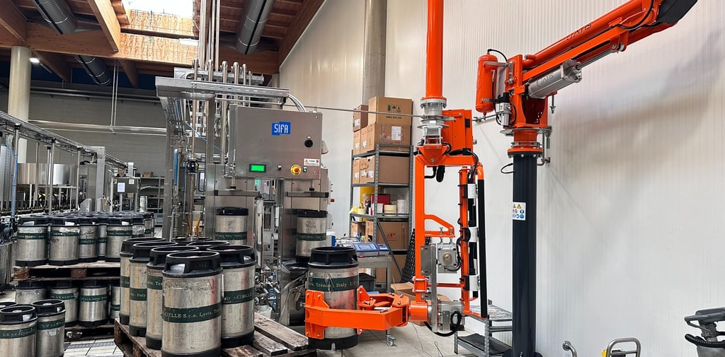
End-of-arm tooling (EOAT) refers to the interface between the manipulator and the part being handled. Unlike robotic EOAT—which operates in highly repeatable, programmed paths—EOAT for pneumatic manipulators must account for human-guided variability, making design considerations around stability, ergonomics, and forgiveness more critical.
A well-designed EOAT system determines:
Whether a part can be handled safely
How efficiently it can be moved
How much effort the operator must apply
Core Design Objectives
Every EOAT design should balance four primary engineering goals:
Secure Retention: Prevent slipping, dropping, or shifting under all expected conditions
Operator Control: Maintain intuitive handling with minimal effort or correction
Part Protection: Avoid deformation, scratching, or surface damage
Cycle Efficiency: Enable fast engagement and release without added complexity
These objectives often compete—for example, increasing grip force improves security but may risk damaging delicate parts—so design requires careful tradeoff management.
Load, Force, and Torque Considerations
Static vs Dynamic Loading
Static load: The weight of the part at rest
Dynamic load: Includes acceleration, deceleration, and operator-induced motion
Dynamic forces can significantly exceed static weight, especially during rapid repositioning.
Safety Factors
Typical engineering safety factors:
2× for stable, controlled environments
3–4× for variable handling or critical safety applications
Center of Gravity (CG)
Offset loads introduce torque:
A part lifted away from its CG creates rotational force
EOAT must counteract this with:
Proper grip placement
Multiple contact points
Structural rigidity
Ignoring CG is one of the most common causes of unstable handling.
EOAT Types and Engineering Applications
Mechanical Finger Grippers (Example: Handling Rolls)
Application Example:
Handling rolls of material (film, paper, foil)
Design Approach:
Use expanding fingers or internal clamping mechanisms inserted into the roll core
Apply outward force evenly to avoid crushing the core
Key Considerations:
Core diameter tolerance variation
Required expansion force vs material strength
Alignment during insertion
Advantages:
Positive mechanical engagement
High control during rotation or tilting
Limitations:
Requires consistent internal geometry
Not suitable for damaged or deformed cores
Vacuum Grippers
(Example: Plastic and Glass Sheets)
Application Example:
Large sheets of plastic or glass
Design Approach:
Use multiple suction cups or foam vacuum plates distributed across the surface
Ensure load is evenly supported to prevent bending
Key Considerations:
Surface condition (smooth, porous, oily)
Vacuum level required for material weight
Cup spacing to prevent deflection
Engineering Insight:
Thin sheets introduce flexural deformation, meaning:
EOAT must support the part structurally, not just lift it
Advantages:
Minimal surface damage
Fast engagement/release
Limitations:
Sensitive to leaks or surface irregularities
Reduced performance on textured or porous materials
Magnetic Grippers (Example: Sheet Steel)
Application Example:
Handling flat sheet steel
Design Approach:
Use permanent or electro-permanent magnets
Size magnetic field strength based on thickness and weight
Key Considerations:
Air gaps (paint, scale, debris reduce holding force)
Sheet thickness (thin sheets reduce magnetic effectiveness)
Residual magnetism concerns
Advantage
Rapid pickup
No mechanical wear surfaces
Limitations:
Only works with ferrous materials
Reduced reliability with surface contamination
Custom Gripping Jaws
(Structural Feature-Based Design)
Application Example:
Machined components or irregular parts
Design Approach:
Design jaws to engage the strongest structural features:
Bosses
Flanges
Internal bores
Use non-marring materials (urethane, nylon, coated metals)
Key Considerations:
Contact stress vs material yield strength
Geometry matching for repeatable positioning
Load distribution across multiple نقاط contact
Engineering Insight:
Gripping by structural features:
Improves stability
Reduces deformation risk
Enables precise orientation control
Advantages:
High precision and repeatability
Custom-fit to application
Limitations:
Requires design and fabrication time
Less flexible for part variation
Surface and Material Interaction
EOAT performance is heavily influenced by surface conditions:
Smooth surfaces → ideal for vacuum
Rough or porous surfaces → require mechanical gripping
Oily or wet surfaces → reduce friction and vacuum effectiveness
Fragile finishes → require compliant or coated contact materials
Material compatibility should always be verified under real conditions.
Compliance and Alignment
Because manipulators are human-guided, EOAT should include compliance features:
Floating mounts
Pivot joints
Shock-absorbing interfaces
These allow:
Minor misalignment correction
Reduced stress on both part and equipment
Smoother operator control
Rigid systems without compliance often lead to binding or operator fatigue.
Ergonomic Integration
EOAT design directly impacts usability:
Handle placement should align with natural wrist posture
Controls should require minimal force
Operator should maintain clear visibility of the part
Poor ergonomic design results in:
Increased fatigue
Reduced precision
Higher likelihood of handling errors
Safety Engineering Considerations
Critical safety features include:
Redundant gripping mechanisms (especially for heavy loads)
Fail-safe designs (e.g., grip maintained during air loss where possible)
Load-rated components with verified margins
Safety should be validated not only for static holding, but also for:
Sudden movement
Operator error
Unexpected load shifts
Integration with the Manipulator System
EOAT must be evaluated as part of the full system:
Total weight must remain within manipulator capacity
Air supply must support all pneumatic components
Mounting interfaces must maintain rigidity and alignment
Improper integration can negate even a well-designed gripper.
Common Failure Modes
Understanding typical failures improves design robustness:
Loss of vacuum seal → dropped parts
Insufficient grip force → slipping or rotation
Improper CG alignment → unstable handling
Over-constrained gripping → part damage or binding
Operator compensation → indicates poor EOAT design
These issues are often systemic, not just component-level.
Practical Design Workflow
A structured EOAT design process:
Define part characteristics (weight, geometry, surface)
Identify handling requirements (orientation, motion, cycle time)
Select appropriate gripping method
Calculate required forces and safety margins
Design contact interfaces
Incorporate compliance and ergonomics
Validate under real operating conditions
Selecting Grippers
EOAT design for pneumatic manipulators sits at the intersection of:
Mechanical engineering
Human factors
Application-specific constraints
Effective solutions are rarely universal—they are context-driven systems designed around the physics of the part and the behavior of the operator.
A rigorous engineering approach to EOAT not only improves handling performance, but also reduces variability, increases safety, and extends the functional capability of the manipulator system itself.
We can help. Tell us about your application at info@atisamerica.com
Frequently Asked Questions (FAQ)
1. How do I choose the right type of EOAT for my application?
Start with three key variables:
Part material (metal, plastic, glass, etc.)
Surface condition (smooth, rough, oily, porous)
Geometry (flat, cylindrical, irregular)
From there:
Use vacuum for smooth, flat, non-porous surfaces
Use magnetic for ferrous metals
Use mechanical or custom jaws for irregular or high-security applications
In many cases, the best solution is not a single method but a hybrid approach.
2. What safety factor should I use when designing EOAT?
A general guideline:
2× safety factor for stable, controlled environments
3–4× safety factor for variable handling, human interaction, or critical loads
Higher safety factors are recommended when:
The cost of failure is high
Load conditions are unpredictable
Operators are directly involved in guiding the system
3. How important is the center of gravity (CG) in EOAT design?
It is critical. Poor CG alignment leads to:
Rotational instability
Increased operator effort
Higher risk of dropping or mispositioning parts
Ideally, the EOAT should:
Engage as close to the CG as possible
Use multiple contact points to control rotation
4. Can one EOAT design handle multiple part types?
It depends on how similar the parts are.
Yes, if parts share:
Similar geometry
Similar weight range
Compatible surface conditions
No, if variations affect:
Grip method (e.g., vacuum vs mechanical)
Structural engagement points
Required precision
In mixed environments, modular or adjustable EOAT designs may be appropriate.
5. What are the most common causes of part dropping?
Typical causes include:
Insufficient gripping force
Loss of vacuum due to leaks or surface issues
Incorrect material assumptions (e.g., porous surface)
Poor CG alignment causing rotation
Most failures are not due to component defects, but design oversights or incorrect assumptions.
6. How do I prevent damage to delicate parts?
Key strategies:
Use compliant materials (urethane, rubber, coated surfaces)
Distribute load across multiple contact points
Avoid excessive clamping force
Design around structural features, not cosmetic surfaces
Testing under real conditions is essential to validate performance.
7. When should I use a custom EOAT instead of a standard solution?
Custom EOAT is typically required when:
Parts have complex or irregular geometry
Standard grippers cannot achieve stable engagement
Precision orientation or repeatability is critical
Surface protection requirements are strict
Standard solutions are effective for simple, repeatable applications—but custom designs provide better control in demanding scenarios.
8. How does EOAT affect operator ergonomics?
EOAT directly influences:
Required handling force
Wrist and arm positioning
Ease of part alignment
Poor EOAT design forces operators to compensate, leading to:
Fatigue
Reduced accuracy
Increased injury risk
Good design minimizes the need for operator correction.
9. What role does compliance play in EOAT design?
Compliance allows the EOAT to:
Absorb minor misalignment
Reduce stress on parts and equipment
Improve handling smoothness
Without compliance, systems become overly rigid, increasing:
Binding
Operator effort
Risk of damage
10. How should EOAT be tested before deployment?
Testing should include:
Full load handling under real conditions
Dynamic movement (not just static holding)
Edge cases (off-center loads, slight misalignment)
Repeated cycle testing
Validation should confirm:
Grip reliability
Operator usability
Safety margins
11. Can EOAT performance degrade over time?
Yes. Common causes include:
Wear on contact surfaces
Vacuum seal degradation
Contamination (oil, dust, debris)
Mechanical loosening or misalignment
Routine inspection and maintenance are necessary to maintain performance and safety.
12. What’s the biggest mistake engineers make in EOAT design?
The most common issue is designing for ideal conditions instead of real ones. This includes:
Ignoring variability in part geometry or surface condition
Underestimating dynamic forces
Overlooking operator interaction
Robust EOAT design accounts for real-world variability, not just theoretical performance.